Yaesu FT-102 Frequently Asked Questions (FAQ)
This page is new in February 2012, and will be an ongoing collection of
Frequently Asked Questions (FAQ) that I receive where I note recurrent
misconceptions. It will be updated from time to time when I see problems arising.
- :Q: Screen Supply Capacitor Bank Leakage ?? (Common user mistake):
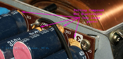
A: Some people mistakenly think that the capacitors for the screen supply
have all leaked (upper chassis on the left of the transformer cage).
(Click
here
for High-Resolution photo)
- :Q:
People ask – why can I not get power out on 160 meters or my plate control
pointer does not match where the frequency is printed?
A. - The plate control in the 102 is somewhat confusing to understand
until you see what Yaesu did to make the control accurate and manageable.
It is quite logical and ingenious once you see the meaning of the markings.
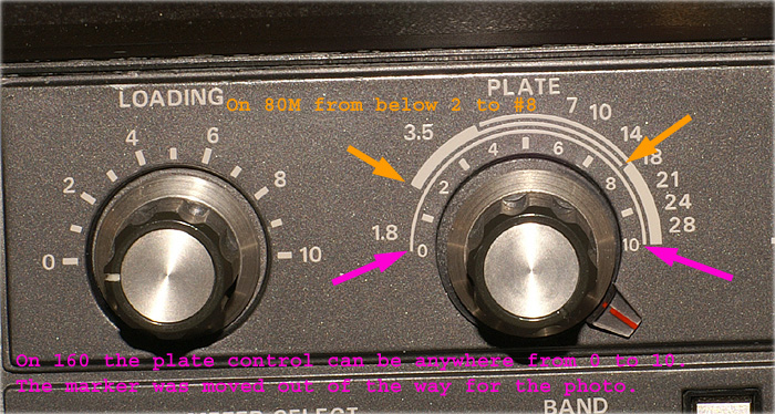
First of all note in the photo above the three curvilinear markings. The
innermost represents 160 meters and is a thin stripe running 180 degrees.
It is marked as 1.8 but that marking really represents the entire hemisphere.
Note the 1.8 designation is the closest to the stripe. The inner markings
range from 0 to 10 and the control can go anywhere in the entire range and
be OK on 160. Its range is marked by the purple arrows. So I tell people to
place the control other than at the innermost marking of 1 or 2 as up to
full clockwise can be OK and retune for maximum power by trial and error.
Next is 80 meters and the 3.5 designation is closest to the fat stripe
which then changes to a thin stripe. The orange arrows point to the beginning
and end of the area of proper function for 80 Mhz. The innermost stripe
indicates from below 2 to the 8 marking as can be seen.
And lastly 7, 10, 14, 18, 21, 24 , and 28 start out as a thin marking
which becomes fat between the 14 and 18 MHZ designation. Any and all of those
frequencies can be located anywhere along that continuous stripe.
So people often ask why their pointer is at the 7 MHz outer most number
when they are on 20 meters (14) and is there a problem? Well as can be seen 7
is in the contiguous stripe for 14 Mhz and so is just fine. (Feb. 2012)
Copyright © 2004-2023 Mal Eiselman NC4L
266094
 (Click here for High-Resolution photo)The truth is that Yaesu used a potting compound at the base of the capacitors to keep the leads from breaking with and from the vibration of shipping. The caps are mounted horizontally and the flexing and vibration will cause the leads to eventually snap. So potting compound was placed like hot glue to stabilize things. With aging, the compound has turned an orange and people say - look at that! - the caps have leaked and so they replace all of them. That is totally unnecessary and just makes collateral damage while doing the unneeded repairs a real problem and for no gain. Remember here that "The road to hell is paved with good intentions". (Feb. 2012)