THE EB5AGV RELAY MODIFICATION |
||||||||||||
Fellow Yaesu FT-102 enthusiasts,
I have often been asked
about the EB5AGV relay modification for RL02 in the FT-102. I am not happy
with this modification for several reasons. I responded to a
fellow ham in an email about this and thought it would be a good
idea to put that letter and photo up on my Yaesu FT-102
website for your enjoyment and education. I hope you enjoy the
explanation and photo.
NC4L
Mal
________________________________________________________________________________________________________________ |
||||||||||||
Hi Fred,
Yes, I have seen the
EB5AGV mod for RL02 several times in radios that I have worked on and it
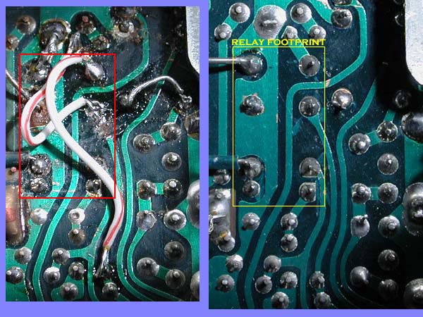
is a mess. I have enclosed a side by side photo of the trace side of the board
for comparison. Because the pinout configuration of that relay is different from the original, several traces
have to be cut and rerouted. This crosses sensitive RF lines and decreases the performance characteristics of the radio.
I am sure you know that
the component and trace placements on the board are not a matter of
happenstance but rather are placed in certain ways after much experimentation by
the designer to improve crosstalk and non wanted signal mixing. The EB5AGV modification changes the benefits
of the manufacturers design by moving the lines and crossing the lines. When I measure blocking dynamic range
of an unmodified radio I get -127 dBM at 20 KC spacing. When I measure this on the modified radios I get -124
dBM which is a halving of the figure. Blocking dynamic range is a measure of front end overload by adjacent strong signals.
In addition it is a very
hard modification for most hams to do. The plastic socket has to be
soldered and wired and the pins are on 1/10 inch distances. If you use anything but a
fine pencil iron and do not have expert proficiency at soldering and perhaps your vision isn't like a teenager, you
will make a mess of this modification. In addition most hams use soldering irons that are too hot and lift the
traces.
The mod does work but at
an expense of performance. But my real complaint about it is that he makes
it look easy and a lot of guys will try it. When they get
into trouble they will be left with a cut board with lifted traces and
will stop working on it out of frustration. And presently
this is probably the main reason that the FT-102 goes to the radio
graveyard.
Check the photos.
Modified board (relay footprint)
Normal Board (relay footprint) |
||||||||||||
 |
||||||||||||
I hope you can see the
cause for my concern that this is on the web.
There is one other
alternative to the RL02 Problem and that is using a small signal relay
made by Teledyne corporation. This relay is enclosed in a metal can and looks like a
transistor with eight leads coming out of it. Small signal relays are a special type and there is no degradation of the
contact resistance over time if only small signals are used.
I like this repair since
the relay is metal enclosed and shielded from RF. It is also a good choice
because a socket does not have to be prepared and there is no
cutting and rerouting of the traces on the board so it is an easy
modification. Unfortunately, some twisting of the
lead wires has to be done since the pin out configuration is not the
same but I figure the loss here would be compensated
for by the fact that the relay is enclosed in metal and shielded
from stray RF. The disadvantage is that the relay is
~$30.00 in cost. The model number is Teledyne # 712-12.
73 de NC4L
Mal |
||||||||||||
Copyright © 2004-2024 Mal Eiselman NC4L
15241