Yaesu power meter modification
Over the years I have been
bothered by the fact that the relative power output meter in the 102 is
under damped in SSB mode. This results in minimal meter movement even though the radio can be
putting out in excess of 200 watts on SSB peaks. This modification will
not in any way affect the set power levels for continuous
wave outputs like CW or FM or Tune. It will however make your meter move
much more responsively and energetically in the Single
Side Band mode
The Modification takes about 10
minutes. It uses one 10uF electrolytic capacitor and two solder
connections. A photo tutorial of the mod follows. It is easy and fun to do and will permit your set to
function better.
The first step is to remove the top
cabinet of the radio and remove the fast-on connectors for the speaker so
that you can place the top case aside.
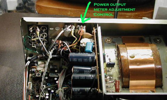
The first photo shows the radio
with the case off and the area where you will be
working. |
|||||||||||||||||
 |
|||||||||||||||||
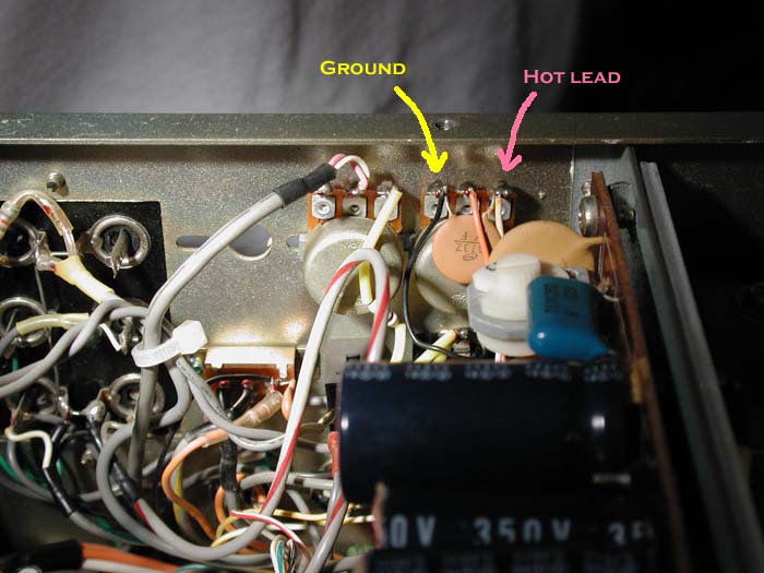
The second photo identifies the
variable pot for adjusting the meter. This pot does not have to be
adjusted but you will have to solder the capacitor onto its outer terminals. The photo identifies the
ground (yellow) and hot (pink) leads. The middle post is the wiper arm and
is not involved in the
modification. |
|||||||||||||||||
 |
|||||||||||||||||
 |
|||||||||||||||||
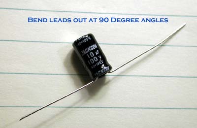
I used a radial lead 10uF
capacitor (both leads come out the same end). The voltage limitation is not very important
because it is in a low voltage circuit. As can be
seen in this photo the leads are bent 90 degrees in opposite directions
so that the cap looks like a ballerina doing a
split.
|
|||||||||||||||||
 |
|||||||||||||||||
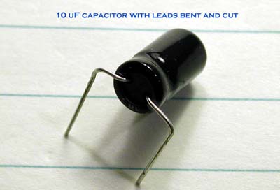
The fourth photo shows that the leads are bent again
at 90 degrees so that they face in the same direction and
are parallel and 1/2 of an inch apart. This will match up with
the terminals on the control. The leads are also trimmed
to about 3/4 of an inch in length from the bend to its far end. Again see photo #4.
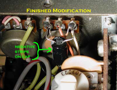
The stripe on the capacitor
indicates the negative terminal and so you solder this to the left lead as indicated in the
photo. The positive lead is soldered to the right
post and that is it.
When you bend the leads note
where the negative stripe is and the orientation of how you will place the cap into
position. If you have done the second bend in the
wrong direction, just rebend the leads. It should look
like the final photo. |
|||||||||||||||||
 |
|||||||||||||||||
Hams are by nature resourceful and
industrious so that if you have an axial lead capacitor at hand (one lead comes
out of each end of the cap) just apply your
intelligence and skill to complete the job.
Now button up the radio and note the
increased responsiveness of the meter. If you want more
movement ---- you guessed it - use a larger capacitor, but it should be an
electrolytic and polarized.
That's it folks. Have fun. I hope
to have more mods in the future.
73 de NC4L
Mal |
|||||||||||||||||
Copyright © 2004-2024 Mal Eiselman NC4L
11720