(Image Source: Page 18 last link below. Click to enlarge)
Additional informtion on the "AZON guided bomb" with a couple of links to
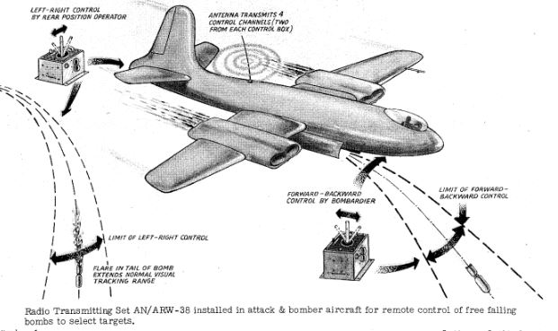
radio equipment actually used, courtesy of Richard Post (KB8TAD).
*The Azimuth “Smart” Bombs of World War II*
The AZON bomb consisted of the tail fin unit being bolted to a 1,000-pound
general purpose bomb. The fins and collar on an assembled bomb made it too
large for transporting in the standard racks and tended to limit the number
of bombs that could be carried to four.
The American AZON Bomb:
The Allies’ guided bomb efforts started in April 1942, when the USAAF
Materiel Command began the development of the azimuth-only (AZON) family of
guided bombs. It was invented by Major Henry J. Rand and Thomas J.
O’Donnell as the answer to the difficult problem of destroying the narrow
wooden bridges that supported much of the Burma Railway. However, AZON was
also used in the European Theater of Operations, as well as in the Pacific
Theater.
The initial variant, designated Vertical Bomb-1 (VB-1), was based on a
1,000-pound bomb that was modified with a new tail unit. A later variant,
the VB-2, was fitted to a 2,000-pound bomb. The tail unit consisted of a
gyroscopic stabilization unit that prevented the bomb from spinning and
weaving in unwanted directions as various corrections were made. Compressed
air kept the gyros spinning during the time of the fall. The VB-1 also had
a 600,000 candela flare for optical tracking, an octagonal shroud with
control surfaces, and a radio command receiver. When a VB-1 was dropped,
the bombardier could track it through his bombsight and use a joystick-type
control to send corrective commands to the bomb. The AZON guidance system
allowed only in-azimuth or lateral course corrections, and errors in range
could not be corrected.
Due to its AZON guidance, the VB-1 was particularly suited to long and
narrow targets like bridges or railways where range errors would be
irrelevant. For normal targets, however, the VB-1 was actually not as good
as unguided freefall bombs because a bomber could not break away
immediately after dropping the bomb, and the accuracy was not effectively
increased because of the lack of range control.
Elevators similar to preset trim tabs were attached to the collar on the
control surfaces of aircraft. The elevators created a stabilizing effect on
the falling bombs, allowing greater ease in altering the missile’s azimuth.
Four braces were connected to the fins to support the aileron and rudder
controls. The four braces were also the antenna for receiving the signal
from the transmitter. The AZON transmitter antenna was located at the rear
of the plane. The antenna was approximately three feet in length. One day a
person who was not connected to the AZON group got curious about the
antenna. He asked what the antenna was used for. A ground crewman, involved
with the AZON equipment and mindful of the high degree of classification
surrounding the project, answered, “It is a highly classified flak
repellent gadget. It keeps the plane from getting hit.”
The bombardier’s joystick control was a BC-1156 pogo stick unit connected
to a BC-1158 radio set that transmitted through the external antenna. Each
aircraft had three antennae mounted beneath its tail section for control
purposes. One transmitted a signal on 475 cycles for left deflection, one
on 3,000 cycles for right deflection, and the third at 30-40 cycles to
activate the smoke-generating system. All three frequencies were changed
periodically to prevent jamming by enemy radio monitoring crews.
The AZON entered production in 1943, after earlier development by USAAF’s
Air Technical Service Command.
Azimuth-only bombs enabled pinpoint bombing of hard-to-hit targets such as
bridges and railways.
*Pictures of the actual equipment* can be found here:
By Joseph Frantiska, Jr.
(See Page 18+, and/or Search on 'AZON' or 'RAZON' for description)
http://hangarthirteen.org/wp-content/uploads/2020/10/Graphic-Survey-of-AAF-Radio-Radar-Equipment-Pt-5.pdf