- ACARA Simplex Frequencies by Band/Service
- Emergency Power Nets Check-in Times
- NOAA Weather
- ARES and Regional Nets
- Local Repeaters
- Public Service
- Dipole Antennas
- Common Formulas
- Sample Net Activation Script
- Note Taking
- NVIS Appendix
This chart (shown below) provides the bands and radio services covered by this plan. They include services available to the general public (such as FRS and CB), as well as license-required services (GMRS and amateur radio bands).
The "Primary" frequency is intended to be the main operational frequency, with the "Alternate" provided to account for a frequency is use by another party, or radio interference. The alternate channel could also be utilized as an avenue for communication not part of the main net.
The mode indicates whether the channel should be monitored in FM, AM, or a sideband mode. The asterisk denoting "NVIS" indicates the use of Near Vertical Incidence Skywave transmissions, which are useful for covering a regional area.
More information on NVIS can be viewed at this YouTube link or in the NVIS Appendix of this document.

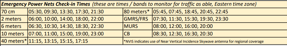
During circumstances which require the use of backup / emergency power, these are the timeslots that each band / service's primary frequency should be monitored for traffic. If possible, the net controller or participant should monitor from 10 minutes til through 10 minutes after the designated time to prevent clock skew issues.
The check-in times are spaced to provide all day coverage with as little use of power as possible, as well as to allow operators to pass traffic between each service as possible. For example, a local neighborhood may share information on FRS or CB that may need conveyed to a community or beyond level. The radio operator could then join an amateur radio band net that would meet that requirement. The 40 and 80 meter check-ins are timed to make best use of band conditions.
Examples:
- At 10am, monitor 146.400 MHz.
- At 16:30 (4:30pm) monitor CB channel 4.
- At 19:30 (7:30pm) monitor FRS channel 16.
- at 11:15am monitor 7.225 MHz lower sideband.
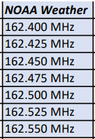
NOAA Weather Radio All Hazards (NWR) is a nationwide network of radio stations broadcasting continuous weather information directly from the nearest National Weather Service office. NWR broadcasts official Weather Service warnings, watches, forecasts and other hazard information 24 hours a day, 7 days a week. (source)
Athens county is primarily served by the following 3 NOAA WR sites:
- KZZ46 - 162.425MHz - Athens, OH
- WXJ47 - 162.475MHz - High Hill, OH
- KJY68 - 162.500MHz - Chillicothe, OH
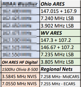
The Amateur Radio Emergency Service (ARES) is licensed amateur radio operators who volunteer to serve during emergencies. This chart provides a listing of the Ohio and West Virginia standard frequencies, and digital operation modes.
MidCARS (Midwest Amateur Radio Service) and ECARS (East Coast Amateur Radio Service) are long-established HF radio nets that operate from 8am to 2:30pm, and 7:30am to 2:00pm respectively.
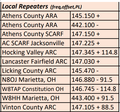
This chart provides many of the locally accessible 2 meter and 70 cm band amateur radio repeaters. While some may have sufficient backup power to operate for a time, in a long term power outage these repeaters will likely go offline.
The listing provides the organization, the output frequency, the repeater offset, and a transmitting PL tone hz if required. For the 2 meter band, the standard repeater offset is 600 kHz. For 70cm, this offset is 5MHz. Refer to example below.
Examples:
- 2 meter repeater with positive offset: listen on 145.150MHz, transmit on 145.750MHz.
- 70 cm repeater with negative offset: listen on 442.100, transmit on 437.100
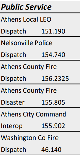
These are a few of the local Athens County area public service frequencies that you can listen to for additional local information.
Dipole antennas are among the simplest to construct from basic materials and provide good performance. This chart shows the general length of one leg (a dipole antenna has two, so you will need two pieces of this length) of a dipole antenna for each band / service.
In an emergency, if you have a length of coax appropriate for your radio, you may simply cut two flexible wires (such as speaker wire or similar) and connect one to the braid, and the other to the center conductor of the conduit. These wires should then be hung at 90 degrees to the coax forming a general "T" shape, with the horizontal bar being the two pieces of wire.
Be careful that the two wires do not touch, and that the braid and center conductor of the coax do not touch. It would be best to solder and tape these connections if possible, but they may also be tightly twisted in an emergency.
For best performance, mount these wires as high as feasible. You may also raise the center portion and extend the legs to form an upside down V using a tree limb and some rope or twine.
Examples:
- To use the 2 meter band, cut two wires of a length one foot, seven and an eight inches long (1' 7-1/8") and connect as described.
- To use the 40 meter band, cut two wires of a length thirty-two feet, four and five-eighths inches (32' 4-5/8")

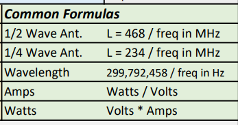
This chart provides some common radio and electrical formulas that you may require in a time of emergency. For quarter and half wave calculations, this could be used to calculate antenna element lengths, or how high to place an antenna. For example, NVIS (near vertical incidence skywave) antennas must be mounted at 1/4 wavelength or lower.
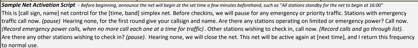
In times of emergency, many individuals with little to no net operation experience may need assistance in getting started. The sample script provides some general guidelines for operation of a radio net during the times and frequencies detailed in this document. It may be modified or used as needed.
Providing assistance to those with critical needs, and collecting and distributing information during emergencies are the most important elements of this plan.
A substantial portion of the document is dedicated to your personal needs and note taking. During an emergency, keeping track of critical information will be imperative.
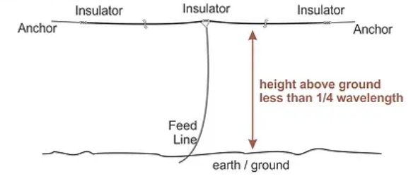
Near Vertical Incidence Skywave (NVIS) antennas are a popular choice for amateur radio operators looking to communicate with other stations within a 0-300 mile range even in difficult terrain or conditions. These antennas are designed to reflect signals off the ionosphere and back down to the earth, making them ideal for short-range communications.
Constructing an NVIS antenna for 40 meters and 80 meters: The easiest and most common way to construct an NVIS antenna for these bands is to use a dipole configuration. Start by cutting two pieces of wire that are each 1/4 wavelength long for the desired frequency. For 40 meters, the wavelength is approximately 66 feet, so the total length of each wire should be around 33 feet. For 80 meters, the wavelength is approximately 134 feet, so the total length of each wire should be around 67 feet. Connect the wires to the center insulator and then spread them apart so that they are parallel to the ground and about 10-15 feet high. Adjust the length of the wires until you find the lowest SWR and the best signal strength.
Author:KD8FKB/WRTP677